Making a Tiny OLED Work on ESP32-C3: Arduino vs Zephyr
SRV February 07, 2026 #zephyr #esp32c3 #riscv #EmbeddedThere's something deeply satisfying about a microcontroller you can actually understand all the way down. The ESP32-C3 is built on RISC-V — an open instruction set architecture — meaning the CPU core itself isn't hidden behind proprietary walls. Espressif publishes a detailed Technical Reference Manual. The toolchain is standard GCC. When something goes wrong, you can trace the problem from your application code through the OS, into the hardware abstraction layer, and down to individual peripheral registers. No black boxes.
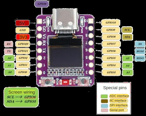
The board I've been working with is the 01space ESP32-C3 0.42" OLED — a tiny PCB, barely larger than your thumb, with a 72x40 pixel SSD1306 OLED soldered directly onto it. No wiring, no breadboard, no jumper cables. Plug it into USB and you have a complete computer with a display.
The Arduino Baseline: It Just Works
In the Arduino ecosystem, getting pixels on this display takes about five minutes. The U8g2 library handles everything:
U8G2_SSD1306_72X40_ER_F_HW_I2C ;
void
void
There are dozens of ready-made examples — games, clocks, sensor dashboards. The library knows about this specific panel: its 72x40 resolution, its position within the SSD1306's 132x64 GDDRAM, the correct initialization sequence. You pick your constructor, call begin(), and draw things.
This is the experience I wanted to replicate in Zephyr.
Moving to Zephyr: How Hard Can It Be?
Zephyr RTOS has first-class support for the ESP32-C3 and includes an SSD1306 display driver. The 01space board even has an upstream board definition with the display node already configured. The plan was simple: enable CONFIG_DISPLAY=y, use the display_write() API, and let the driver handle everything.
The board's device tree defines the display like this:
eastrising_72x40: ssd1306@3c {
    compatible = "solomon,ssd1306fb";
    reg = <0x3c>;
    width = <72>;
    height = <40>;
    segment-offset = <28>;
    multiplex-ratio = <0x27>;
    prechargep = <0x22>;
    segment-remap;
    com-invdir;
};
I wrote a simple bouncing ball demo using the display API, flashed it, and got... artifacts. Garbled pixels, interleaved rows, nothing resembling a ball or a rectangle.
This is where the investigation began.
Down the Rabbit Hole
Suspicious DTS Values
The SSD1306 controller has a 132x64 pixel GDDRAM — much larger than the 72x40 physical panel. The panel sits in a window within this memory, and several device tree properties control that mapping.
The horizontal centering should place the 72-pixel panel at column 30: (132 - 72) / 2 = 30. The board definition has segment-offset = <28>.
The multiplex ratio controls how many COM (row) lines the controller drives. The board sets it to 0x27 (39 decimal) for the 40-row panel. This seems logical, but the SSD1306 has two COM pin mapping modes — sequential and alternative — and in alternative mode (the default), the COM pins are interleaved: COM0 drives row 0, COM1 drives row 32, COM2 drives row 1, and so on. With MUX=39, only COM0-COM39 are scanned, which with alternative mapping means you get rows 0-19 and rows 32-51 but skip rows 20-31. This could explain interleaved artifacts.
U8g2 sets MUX to 63 for this panel — driving all 64 COM lines even though only 40 are physically connected. So I created an overlay:
&eastrising_72x40 {
    height = <64>;
    multiplex-ratio = <0x3f>;
    segment-offset = <30>;
    prechargep = <0xf1>;
};
Flashed again. Still artifacts.
Suspicious I2C Driver Code
The Zephyr SSD1306 driver sends all data using i2c_burst_write(), which internally creates two I2C messages — a 1-byte control byte (0x00 for commands, 0x40 for data) followed by the actual payload:
/* zephyr/include/zephyr/drivers/i2c.h — i2c_burst_write() */
msg.buf = &start_addr; /* control byte */
msg.len = 1;
msg.flags = I2C_MSG_WRITE; /* no STOP */
msg.buf = buf; /* payload */
msg.len = num_bytes;
msg.flags = I2C_MSG_WRITE | I2C_MSG_STOP;
The first message holds the bus (no STOP). The second continues the transaction. I traced this into the ESP32 I2C driver and found a recovery check inside the per-message loop:
/* zephyr/drivers/i2c/i2c_esp32.c — i2c_esp32_transfer() */
for
This looked like a smoking gun. After message 0 completes without STOP, the bus is legitimately held — bus_busy should be true. The driver would see this, interpret it as a stuck bus, and fire i2c_hw_fsm_reset() — which turns off the I2C clock, sends 9 SCL clear-bus pulses, and reinitializes the peripheral. Message 1 would then try to continue a transaction that no longer exists.
I moved the check before the loop:
if
for
Rebuilt, flashed. Still artifacts. The theory was plausible, but fixing it changed nothing. Maybe bus_busy isn't actually set after an END command without STOP. Maybe the FSM reset never triggers in this path. Without a logic analyzer on the I2C lines, I can't say for certain.
Patching the SSD1306 Driver
I tried eliminating i2c_burst_write() entirely from the SSD1306 driver, replacing it with single-message i2c_write() and the control byte prepended into the buffer:
static int
I also added the deactivate scroll command (0x2E) to the init sequence, which U8g2 sends but the Zephyr driver doesn't.
Still artifacts. At this point I had modified the I2C driver, the SSD1306 driver, and the device tree configuration. None of it helped, individually or combined.
What Actually Worked
I stepped back and asked: what's actually different between U8g2 and the Zephyr driver stack? Not "what looks suspicious in the code," but what hits the I2C bus differently?
U8g2 uses page addressing mode (0x20, 0x02) with explicit page and column commands before each write. The Zephyr SSD1306 driver uses horizontal addressing mode (0x20, 0x00) with column and page range commands. U8g2 sends a known-good init sequence tuned for this specific 72x40 panel. The Zephyr driver assembles its init sequence from device tree properties. The sequences differ in ordering, in which commands are included, and possibly in subtle timing.
Any one of these differences might be harmless on other platforms. I couldn't pinpoint which one matters on the ESP32-C3, or whether it's a combination. But I could replicate exactly what works.
The fix: bypass the Zephyr display driver entirely, talk to the SSD1306 over raw I2C, and match U8g2's approach as closely as possible:
/* Single-message command write: [0x00] [cmd bytes...] */
static int
/* Per-page flush: [0x40] [72 data bytes] = 73 bytes total */
static void
The init sequence matches U8g2: display off, deactivate scroll, MUX 63, page addressing mode, alternative COM pins, charge pump on, display on. Every I2C transaction is a single message with the control byte baked into the buffer.
The prj.conf drops CONFIG_DISPLAY entirely in favor of raw I2C:
CONFIG_I2C=y
Clean bouncing ball, no artifacts.
Full source of the app with the project setup can be found on GitHub
What I Learned
I don't actually know what the root cause is. I found several things that looked wrong — the DTS values, the FSM recovery check, the multi-message transfer pattern — and built plausible theories for each. But fixing them didn't help, so I can't claim any of them were the actual problem. It could be one of them, a combination, or something else entirely that I missed. Without a logic analyzer to see what's actually happening on the I2C bus, this remains an open question.
The SSD1306's GDDRAM is larger than your panel. A 72x40 display sits inside a 132x64 memory space. The segment offset, multiplex ratio, and COM pin mapping all interact. The board's DTS values don't match the datasheet math, though I can't prove this was causing the visible artifacts since correcting them alone didn't help.
"It works in Arduino" is the most useful debugging signal. When U8g2 works flawlessly on the same hardware, the problem isn't the display or the wiring. It means a known-good I2C byte sequence exists. The pragmatic path is to replicate that sequence exactly rather than debug an abstraction stack with too many moving parts.
Sometimes bypassing the abstraction is the honest answer. The Zephyr display driver and SSD1306 abstraction are well-designed for portable code. But when the result is artifacts and you can't isolate why, dropping to raw I2C — matching exactly what works — gets you a working display today. The investigation into why the driver path fails can continue separately, ideally with proper I2C bus instrumentation.